
INSTRUCTIONS TO CANDIDATES
- Mathematical tables and non-programmable calculators may be used.
- This paper consists of section A and section B.
- ALL working MUST be clearly shown.
Section A (25 marks)
- An object pin is placed in front of a plane mirror. The image of the pin is viewed from position A. Draw array diagram to show this image. (2 marks)
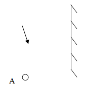
Figure 1 - You are provided with two rods, a conductor and an insulator. Describe how you would use a charged gold-leaf electroscope to distinguish between the insulator and a conductor. (2 marks)
- A pin-hole camera of length 10 cm is placed 0.5m away from a goalpost. A sharp image of the goalpost 15 cm high is formed on the screen. Determine the height of the goalpost. ( 2 marks)
- The figure 2 below shows a displacement- time graph of a particular progressive wave.
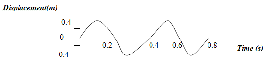
Figure 2
Draw on the same diagram, a wave which passes through the points with double frequency and half amplitude of the first wave. (2 marks) - Explain how temperature affects the speed of sound is gases (1 mark)
- A polythene charged strip is brought near two spheres A and B that are in contact as shown in figure 3.
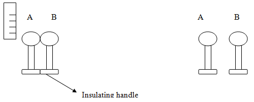
Figure 3(a) Figure 3(b)- indicate the charge distribution the spheres when negatively charged polythene is brought near A. (1 mark)
- draw the charge distribution on A and B shown in (b) when the spheres are separated and immediately polythene withdrawn. (2 marks)
- Three identical lamps X, Y, Z are connected as in figure 4. The E.m.f applied in the circuit 3.0 volts
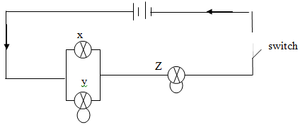
Figure 4.- State which lamp is brightest when circuit is closed? (1 mark)
- Explain your answer in part (i) above. (2marks)
- Figure 5 shows an iron rod on which a wire is to be wound to make an electromagnet.
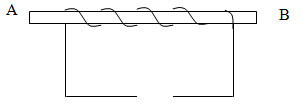
Figure 5
By drawing, show how two cells are connected so that end A becomes North pole and end B south pole. (2marks) - The force on a conductor carrying current in a magnetic field can be varied by changing, among others, the magnitude of the current and magnetic field strength. State two other factors that can be changed to vary the force. (2marks)
- Using domain theory explain the differences between a magnetic material and a magnet (2marks)
- Figure 6 shows water waves traveling from deep into shallow water.
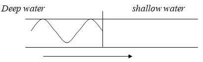
Figure 6
Complete the wave front to show how it travels in shallow water (1 mark) - Figure 7. Shows two rays incident on a converging lens
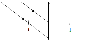
Figure 7.- Draw the ray after refraction to show positions of the image. (2marks/)
- State the application of this arrangement in (i) above (1 mk).
Section B(55 marks)
-
- Define refractive index of a material in terms of velocity of light. (1mark)
- state the conditions necessary for a total internal refraction to occur (2marks)
- Figure 8 shows light ray traveling from air to glass and from glass to air. Ray of Light AO is incident normally on the semicircular glass,
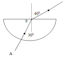
Figure 8- Determine the refractive index of glass with respect to air. (3 marks)
- In addition to the circular glass, you are provided with; a ray box (source of light ray), four office pins, soft board, white paper and a protractor, describe how this apparatus may be used to determine the critical angle of the glass. (4marks)
- Determine the critical angle of this semicircular glass. (3 marks)
-
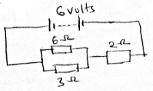
- you are provided with three resistors 1 Ω, 3 Ω and 6 Ω.
- Draw a circuit diagram to show 6Ω and 3Ω resistors in parallel and this combination in series with 2Ω resistor and the 6 V battery. (2marks).
- Determine the total effective resistance in the circuit drawn in (i) above (2 marks)
- Calculate the p.d across a 2 Ω resistor (2 marks)
- Determine the value of current through the 6 Ω resistor (3marks)
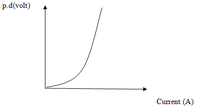
Figure 9.
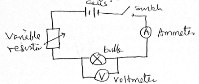
- Figure 9, shows a graph of potential difference (V) against current (I A) through a filament lamp (bulb)
- Draw a well labeled working circuit diagram showing the apparatus that can be used to obtain a set of readings used to draw the graph in (figure9). (2marks)
- explain why the filament lamp does not obey ohm’s law (2 marks)
- Explain how resistance of the filament lamp varies as current increases. (1 mark).
- State the characteristics of material wire used in the filament lamp. (1 mark).
- you are provided with three resistors 1 Ω, 3 Ω and 6 Ω.
-
- define capacitance of a capacitor. (1 mark)
-
- Describe the essential features in the construction of a parallel plate capacitor. (3 marks)
- Explain how charge is distributed in such parallel capacitor in b(i) above. (2marks)
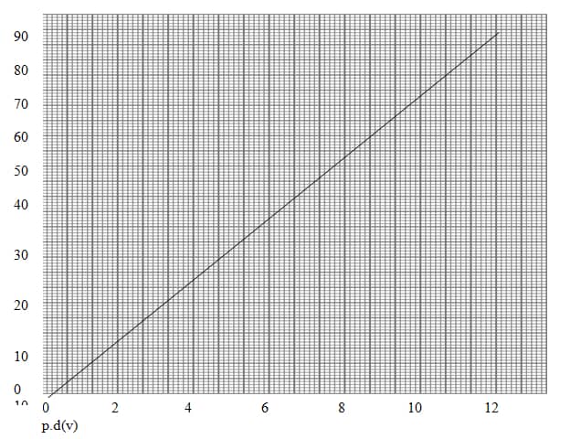
- In an experiment to charge a capacitor, the charge stored was measured for different values of charging potential difference. A graph of charge stored Q (µc) (y-axis) against potential difference p.d (v) was plotted as shown graph 1
- list down the apparatus used to perform this experiment (1 mark)
- draw a circuit diagram showing all connections of the listed apparatus in (i) above to perform the experiment of charging a capacitor. (2 marks)
From the graph - determine the capacitance of the capacitor used in this experiment. (3 marks)
- Calculate the energy stored in this capacitor. (2 marks)
- Three capacitors are connected a shown in figure 10.
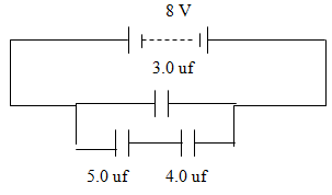
Figure 10
Calculate:- total effective capacitance in the circuit. (2 marks)
- The charge on a 4.0 µF capacitor. (2 marks)
-
- Complete figure 11 by drawing two rays to show the final image formed by convex lens of the object O, shown
(2 marks)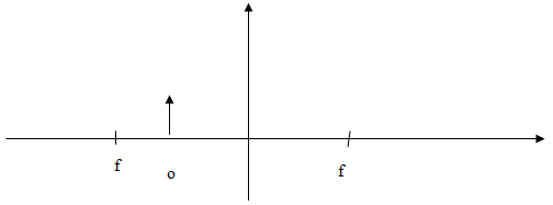
Figure 11 - Describe the characteristics of the image formed in 16 (a) above (3 marks)
- State the optical device that uses the arrangement in (a) above. (1 mark)
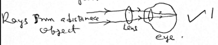
- A person viewing a near object switches attention to look at an aero-plane far away.
- State the change that occurs in his eye in order to see the aero-plane clearly. (2 marks)
- If this person fails to see the aero-plane clearly, what defect is he suffering from? (1 mark)
- Explain with a diagram how the defect can be corrected. (3 marks)
- Complete figure 11 by drawing two rays to show the final image formed by convex lens of the object O, shown

MARKING SCHEME
Section A (25 marks)
- An object pin is placed in front of a plane mirror. The image of the pin is viewed from position A. Draw array diagram to show this image. (2 marks)
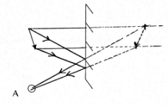 Position of image ✓1 Rays of light ✓1
Figure 1 - You are provided with two rods, a conductor and an insulator. Describe how you would use a charged gold-leaf electroscope to distinguish between the insulator and a conductor. (2 marks)
- Bring each rod near the cap of a charged gold leaf electroscepe
- A conductos will discharge an electroscope while an insulator has no effect on charged electroscope
- A pin-hole camera of length 10 cm is placed 0.5m away from a goalpost. A sharp image of the goalpost 15 cm high is formed on the screen. Determine the height of the goalpost. ( 2 marks)
HI = v
Ho u
15 = 10
Ho 500
Ho = 15 × 50 = 75m
10
Height Ho of goalpost = 75m - The figure 2 below shows a displacement- time graph of a particular progressive wave.
Draw on the same diagram, a wave which passes through the points with double frequency and half amplitude of the first wave. (2 marks)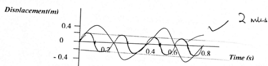
Figure 2
Period T1 = 0.4(s)
Frequency f1 = 1/T1 = 2.5Hz
Frequency f2 = 2f1 = 5.0Hz
Period T2 = 1/f2 = 0.2(s) - Explain how temperature affects the speed of sound is gases (1 mark)
- Increase in temperature increases vibrations of air particles, thus collusion between increases and faster transmission of sound Energy
- A polythene charged strip is brought near two spheres A and B that are in contact as shown in figure 3.
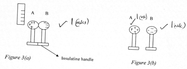
- indicate the charge distribution the spheres when negatively charged polythene is brought near A. (1 mark)
- draw the charge distribution on A and B shown in (b) when the spheres are separated and immediately polythene withdrawn. (2 marks)
- Three identical lamps X, Y, Z are connected as in figure 4. The E.m.f applied in the circuit 3.0 volts
Figure 4.- State which lamp is brightest when circuit is closed? (1 mark)
- Bulb Z
- Explain your answer in part (i) above. (2marks)
- Bulb x and y share the current of the main source but bulb Z receives the total current form main source
- State which lamp is brightest when circuit is closed? (1 mark)
- Figure 5 shows an iron rod on which a wire is to be wound to make an electromagnet.
By drawing, show how two cells are connected so that end A becomes North pole and end B south pole. (2marks)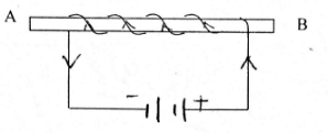
Figure 5
Cell shown correctly - 1mk
Direction of current - 1mk - The force on a conductor carrying current in a magnetic field can be varied by changing, among others, the magnitude of the current and magnetic field strength. State two other factors that can be changed to vary the force. (2marks)
- Length of the conductor/increasing number of turns of the coil
- Using a soft iron core or winding wire on soft iron
- Using domain theory explain the differences between a magnetic material and a magnet (2marks)
- In a Magnet, all dipoles are alligmed to face one direction
- In a Magnetic Material, dipoles exist in loops that make it neutral.
- Figure 6 shows water waves traveling from deep into shallow water.
Complete the wave front to show how it travels in shallow water (1 mark)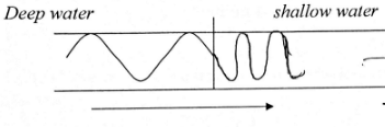
Figure 6- The crest and troughs are close to each other
- Wavelength is reduced
- Figure 7. Shows two rays incident on a converging lens
- Draw the ray after refraction to show positions of the image. (2marks)
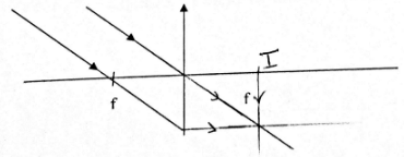 Positioning of image - 1 mk Intersecting rays - 1mk
 - State the application of this arrangement in (i) above (1 mk).
- Telescope eyepiece
- Draw the ray after refraction to show positions of the image. (2marks)
Section B(55 marks)
-
- Define refractive index of a material in terms of velocity of light. (1mark)
- Is the ration of speed of light in air to the speed of light in the Material
- state the conditions necessary for a total internal refraction to occur (2marks)
- Light must travel from more optically denser medium to a less optically dense medium
- Light travels slower in an optically denser medium compared to the optically rarer medium.
- Figure 8 shows light ray traveling from air to glass and from glass to air. Ray of Light AO is incident normally on the semicircular glass,
Figure 8- Determine the refractive index of glass with respect to air. (3 marks)
sin i = gna
sin r
ang = 1 = sin r = sin 40 = 1.286 (reversibility of light principle)
gna sin i sin 30 - In addition to the circular glass, you are provided with; a ray box (source of light ray), four office pins, soft board, white paper and a protractor, describe how this apparatus may be used to determine the critical angle of the glass. (4marks)
- Trace the semicircular glass in a white paper fixed in soft board.
- Remove the glass and draw a normal line at middle of flat side of the trace.
- Measure ray i = 10° on left side of the normal on curved part of the circular glass.
- Place ray box so that light is about 10° from the normal and observe the refracted ray from the flat side.
- Increase the angle between normal and light ray until the refracted ray follows the boundary. Measure
angle is incident which is the critical angle
- Determine the critical angle of this semicircular glass. (3 marks)
Sin c = 1 = sin i = sin 30
ang sin r sin 40
c = sin−1(0.7799)
= 51.1
- Determine the refractive index of glass with respect to air. (3 marks)
- Define refractive index of a material in terms of velocity of light. (1mark)
-
- you are provided with three resistors 1 Ω, 3 Ω and 6 Ω.
- Draw a circuit diagram to show 6Ω and 3Ω resistors in parallel and this combination in series with 2Ω resistor and the 6 V battery. (2marks).
 working current - 1mk position of resistors - 1mk
 - Determine the total effective resistance in the circuit drawn in (i) above (2 marks)
RT = 6 × 3 + 2
6 + 3
= 4Ω - Calculate the p.d across a 2 Ω resistor (2 marks)
I = V/R = 6/4 = 1.5A
V across 2Ω = IR
= 1.5 × 2
= 3.0V - Determine the value of current through the 6 Ω resistor (3marks)
V across the parallel = 6 − 3 = 3V
I through 6Ω = V/R = 3/6 = ½ = 0.5A
Figure 9.
- Draw a circuit diagram to show 6Ω and 3Ω resistors in parallel and this combination in series with 2Ω resistor and the 6 V battery. (2marks).
- Figure 9, shows a graph of potential difference (V) against current (I A) through a filament lamp (bulb)
- Draw a well labeled working circuit diagram showing the apparatus that can be used to obtain a set of readings used to draw the graph in (figure 9). (2marks)
- explain why the filament lamp does not obey ohm’s law (2 marks)
- At high current, temperature of wire increases and therefore voltage does not increase linearly as current further increases.
- Explain how resistance of the filament lamp varies as current increases. (1 mark).
- As current increases, number of vibrations of atoms increases and this opposes smooth flow of electrons.
- State the characteristics of material wire used in the filament lamp. (1 mark).
- Thin wire and long
- High resistance wire
- Draw a well labeled working circuit diagram showing the apparatus that can be used to obtain a set of readings used to draw the graph in (figure 9). (2marks)
- you are provided with three resistors 1 Ω, 3 Ω and 6 Ω.
-
- define capacitance of a capacitor. (1 mark)
- It is the charge stored in a capacitor for unit volt.
-
- Describe the essential features in the construction of a parallel plate capacitor. (3 marks)
- Two parallel metal plates or electrodes
- An Insulating material between them .
- Two wires, one leading to +ve terminal of a cell to one plate (+ve) and the other to negative terminal of a cell.
- Explain how charge is distributed in such parallel capacitor in b(i) above. (2marks)
- Negative charges from -ve terminal accumulate at -ve plate and an equal number of +ve charges accumulate at +ve plate.
- Describe the essential features in the construction of a parallel plate capacitor. (3 marks)
- In an experiment to charge a capacitor, the charge stored was measured for different values of charging potential difference. A graph of charge stored Q (µc) (y-axis) against potential difference p.d (v) was plotted as shown graph 1
- list down the apparatus used to perform this experiment (1 mark)
- variable resistor
- low voltage cell
- capacitor
- milliameter/Galvanometer
- voltmeter
- switch
- draw a circuit diagram showing all connections of the listed apparatus in (i) above to perform the experiment of charging a capacitor. (2 marks)
From the graph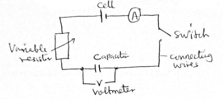
- determine the capacitance of the capacitor used in this experiment. (3 marks)
C = Q/V = gradient of the line
= (60 − 30) × 10−6
8 − 4
= 7.5μF - Calculate the energy stored in this capacitor. (2 marks)
Energy = ½Q
= ½ × 90 × 10−6 C × 12
= 5.40 × 10⁻⁴ joules
- list down the apparatus used to perform this experiment (1 mark)
- Three capacitors are connected a shown in figure 10.
Figure 10
Calculate:- total effective capacitance in the circuit. (2 marks)
CT = 5 × 4 + 3
4 + 5
= 5.222μF - The charge on a 4.0 µF capacitor. (2 marks)
Q = CV
= 5.222 × 10−6 × 8
= 41.78 × 10⁻⁶C
Q3Ω = 3 × 10−6 × 8
= 24 × 10−6C
Qin 4Ω = (41.78 − 24) × 10−6
= 17.78 × 10−6
= 1.778 × 10⁻⁵C
- total effective capacitance in the circuit. (2 marks)
- define capacitance of a capacitor. (1 mark)
-
- Complete figure 11 by drawing two rays to show the final image formed by convex lens of the object O, shown
(2 marks)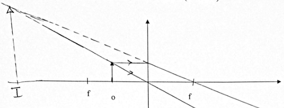
Figure 11
Position of image - 1mk
Two intersecting produced lines - 1mk - Describe the characteristics of the image formed in 16 (a) above (3 marks)
- Erect/upright
- Virtual
- Magnified
- Same side as object
- State the optical device that uses the arrangement in (a) above. (1 mark)
- Eyepiece of a compound microscope
- A person viewing a near object switches attention to look at an aero-plane far away.
- State the change that occurs in his eye in order to see the aero-plane clearly. (2 marks)
- The ciliary muscles relax and the lens has a flattened shape.
- If this person fails to see the aero-plane clearly, what defect is he suffering from? (1 mark)
- Long sightedness (hypermetropia)
- Explain with a diagram how the defect can be corrected. (3 marks)
- A converging lens is used to refract the rays of light before the eye lens refracts than further
- A converging lens is used to refract the rays of light before the eye lens refracts than further
- State the change that occurs in his eye in order to see the aero-plane clearly. (2 marks)
- Complete figure 11 by drawing two rays to show the final image formed by convex lens of the object O, shown
Join our whatsapp group for latest updates
Tap Here to Download for 50/-
Get on WhatsApp for 50/-
Download Physics Paper 2 Questions and Answers - Joint Pre-Mock Exams 2021/2022.
Tap Here to Download for 50/-
Get on WhatsApp for 50/-
Why download?
- ✔ To read offline at any time.
- ✔ To Print at your convenience
- ✔ Share Easily with Friends / Students