
Instructions to candidates
- This paper consists of TWO sections : A and B
- Answer ALL the questions in section A and B in the spaces provided
- All working MUST be clearly shown
- Mathematical tables and non-programmable silent electronic calculators may be used.
SECTION A (25mks)
Answer all questions in this section the spaces provided
- Figure 1 below shows a plotting compass placed between two strong magnets.
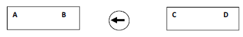
- Give the polarity of the end D of the right hand magnet. (1mark)
- Draw on the diagram the resulting magnetic field pattern between B and C. (2marks)
- State one property of an image formed by a convex mirror. (1mark)
- An opaque object is placed before a light source as shown in figure 2 below.
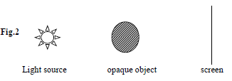
Draw rays in the diagram to show how the shadow is formed. (2marks) - In the circuit diagram in figure 3 below, the voltmeter and ammeter read 4v and 40 mA respectively.
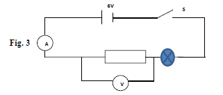
Determine the resistance of the filament of the bulb. (3marks) - Name the electromagnetic wave that borders both x-rays and visible light. (1mark)
- A dry cell is not recharged once used up. However when used well, it can serve someone for some time. State two precautions necessary when using it other than storing it in dry condition. (2marks)
- Give one observable change on water waves when passed from deep to shallow water.(1mark)
- Figure 4 below shows a conductor in a uniform magnetic field carrying current in the direction shown.
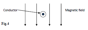
Indicate on the diagram the direction of motion of the conductor. (1mark) - Name the property of light applied in transmitting light signal in optical fibres. (1mark)
- A heater of resistance R1 is rated P watts, V volts while another of resistance R2 is rated 2P watts, V/2 volts. Determine R1/R2. (3marks)
- Figure 5 shows light passing through a transparent block.
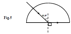
Determine the refractive index of the block. (2 marks) - What position should a small boy stand in front of a concave mirror to view his;
- Enlarged and upright image in a barber shop? (1mark)
- Enlarged and inverted image in a fashion modeling room? (1mark)
- Figure 6 below shows a wave profile for a wave whose frequency is 2.5Hz
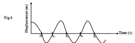
Determine the value of t3 (3 marks)
SECTION B (55MKS)
Answer all questions in this section the spaces provided -
- What is dioptres? (1mark)
- State two differences between the eye and lens. (2marks)
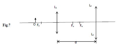
- A compound microscope with objective lens L1 of focal length 0.8cm and an eyepiece lens L2 of focal length 2.5cm is shown in the figure 7 below. An object O is placed in front of the objective lens at a distance u1 of 1.2cm. The system forms a final image I2 at a distance of 10cm from L2. Determine the distance of separation, d, of lenses L1 and L2. (3marks)
- The figure 8 below shows an experimental set up consisting of a mounted lens, L, a screen, S, a metre rule and a candle.
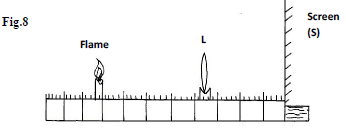
- Describe how the set up may be used to determine the focal length f, of the lens. (4marks)
- State why the set up would not work if the lens were replaced with a diverging lens. (1mark)
- An object is placed 20cm from a converging lens of focal length 8cm. Determine how far the image is from the object. (3marks)
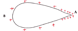
- Figure 9 below shows a pear shaped conductor with positive charge on its surface.
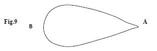
- A proof plane is used to touch side B of the conductor and then the cap of an uncharged electroscope. This is then repeated with side A.
- Give the observation made on the electroscope in each case. (2marks)
B…………………………………………………………………………………………………………………………………
A………………………………………………………………………………………………………………………………... - What conclusion is drawn from the observation in (i) above. (1mark)
- Give the observation made on the electroscope in each case. (2marks)
-
- Draw on the diagram above, the illustration of your conclusion in (ii) above. (1mark)
- Name one application of such a conductor. (1mark)
- Figure 10 below shows the charged plates of a parallel plate capacitor where the distance of separation, d is small.
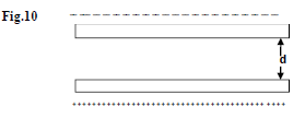
- Complete the diagram to show the electric field pattern in the space between the plates. (2marks)
- Without changing the distance d between the plates, suggest one method by which you could increase the capacitance. (1mark)
- State a device where a variable air capacitor could be used. (1mark)
- Figure 11 below shows a circuit of three capacitors and a d.c. source.
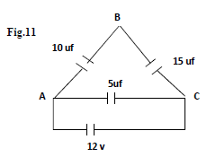
Determine the p.d. across A.B. (3marks)
- A proof plane is used to touch side B of the conductor and then the cap of an uncharged electroscope. This is then repeated with side A.
- Figure 12 below shows the path of a ray of yellow light through a glass prism of refractive index 1.60.
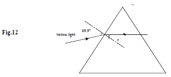
- Determine the value of angle r. (3marks)
- Show on the figure the critical angle, c and determine its value. (3marks)
- Determine the speed of light in glass given that the speed of light in vacuum.
(C = 3.0x10⁸m/s) (3marks) - On the same figure, sketch the path of the light after striking the prism if the prism was replaced by another of similar shape but lower refractive index. (Use dotted line for your answer) (2marks)
- Figure 13 below shows the circuit of a simple telephone receiver. When a person speaks into the microphone on the other side a varying current flows.
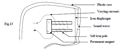
- State the reason why the solenoids are wound in opposite directions around the soft-iron pole pieces as shown. (1mark)
- Explain how the speech current from the microphone is converted into sound in the receiver. (3marks)
- State and explain the effect of replacing the soft iron pole pieces with steel pole pieces. (3marks)
-
- State the Ohms’ law. (1mark)
- Three resistors x,y and z where x = 200 Ω, y = 100 Ω and z is unknown resistance are connected in parallel. This arrangement is then placed in a circuit and current passing through, and potential difference across its measured the table below shows the result.
p.d(V) 2.0 4.0 6.0 8.0 10.0 12.0 Current(l) (A) 0.10 0.20 0.30 0.40 0.50 0.60 - Plot a graph of p.d against current. (5marks)

- Use your graph to calculate the value of unknown resistance. (3marks)
- Plot a graph of p.d against current. (5marks)
- Four resistors are connected in a circuit as shown in the diagram below
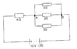
Calculate the p.d across AB. (3marks)

MARKING SCHEME
SECTION A (25mks)
Answer all questions in this section the spaces provided
- Figure 1 below shows a plotting compass placed between two strong magnets.
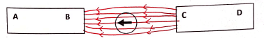
- Give the polarity of the end D of the right hand magnet. (1mark)
South pole - Draw on the diagram the resulting magnetic field pattern between B and C. (2marks)
- Give the polarity of the end D of the right hand magnet. (1mark)
- State one property of an image formed by a convex mirror. (1mark)
Upright
Diminished
Virtual - An opaque object is placed before a light source as shown in figure 2 below.
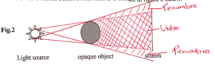
Draw rays in the diagram to show how the shadow is formed. (2marks) - In the circuit diagram in figure 3 below, the voltmeter and ammeter read 4v and 40 mA respectively.
Determine the resistance of the filament of the bulb. (3marks)
Rtotal = R =V/I = 6/0.04 = 150
Resistance of the resisitor = V/I = 4/0.04 = 100
Resistance of the filament of the bulb = 150 - 100 = 50
Alternatively
Voltage across bulb = 6 - 4 = 2V
therefore R = V/I = 2/0.04 = 50 - Name the electromagnetic wave that borders both x-rays and visible light. (1mark)
Ultra-Violet Radiation - A dry cell is not recharged once used up. However when used well, it can serve someone for some time. State two precautions necessary when using it other than storing it in dry condition. (2marks)
Do not draw large current from it
Do not short circuit its terminals - Give one observable change on water waves when passed from deep to shallow water.(1mark)
Wavelengths reduces/decreases
Velocity of the wave reduces/increases - Figure 4 below shows a conductor in a uniform magnetic field carrying current in the direction shown.
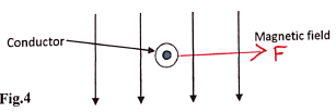
Indicate on the diagram the direction of motion of the conductor. (1mark) - Name the property of light applied in transmitting light signal in optical fibres. (1mark)
Total internal reflection - A heater of resistance R1 is rated P watts, V volts while another of resistance R2 is rated 2P watts, V/2 volts. Determine R1/R2. (3marks)
P = V 2 ⇒ R = V 2
R P
R1 = V2
P
and R2 = (V/2)2
2P
R1 = V2 x P = 8
R2 P V2 - Figure 5 shows light passing through a transparent block.
Determine the refractive index of the block. (2 marks)
n = 1 = 1 = 1.5
SinC sin41.8 - What position should a small boy stand in front of a concave mirror to view his;
- Enlarged and upright image in a barber shop? (1mark)
Between F and the pole - Enlarged and inverted image in a fashion modeling room? (1mark)
Between F and C
- Enlarged and upright image in a barber shop? (1mark)
- Figure 6 below shows a wave profile for a wave whose frequency is 2.5Hz
Determine the value of t3 (3 marks)
T = 1/f =1/2.5 = 0.45
T = 0.45
t3 = 5/4 x 0.4
= 0.5Hz
SECTION B (55MKS)
Answer all questions in this section the spaces provided -
- What is dioptres? (1mark)
A unit for expressing the power of a lens, or mirror equal to the reciprocal of its focal length in metres - State two differences between the eye and lens. (2marks)
Eye Lens Variable focal length
Constant image distance
Constantly changing picturesFixed focal length
Variable image distance
Only one photograph can be taken at a time - A compound microscope with objective lens L1 of focal length 0.8cm and an eyepiece lens L2 of focal length 2.5cm is shown in the figure 7 below. An object O is placed in front of the objective lens at a distance u1 of 1.2cm. The system forms a final image I2 at a distance of 10cm from L2. Determine the distance of separation, d, of lenses L1 and L2. (3marks)
For the 1st image
1/v = 1/f - 1/u = 1/0.8 - 1/1.2
v = 2.4cm
But d = v + u2
Hence u2 = d - v
to find u2 also 1/u2 = 1/f - 1/v = 1/2.5 - 1/102
u = 3.333cm
d = v + u2
=2.4 + 3.333
= 5.733cm - The figure 8 below shows an experimental set up consisting of a mounted lens, L, a screen, S, a metre rule and a candle.
- Describe how the set up may be used to determine the focal length f, of the lens. (4marks)
The candle is placed at a distance from the lens; the screen position is adjusted until a sharp image of the flame is obtained
The image distance,V, from the lens & screen is measured
The process is repeated for other values of U & V; for each set of U and V focal length if S found using the formula; 1/f = 1/v + 1/u
f = average values of f - State why the set up would not work if the lens were replaced with a diverging lens. (1mark)
Diverging lens from virtual images that cannot be formed on the screen - An object is placed 20cm from a converging lens of focal length 8cm. Determine how far the image is from the object. (3marks)
1/f = 1/v + 1/u
1/v = 1/f - 1/u = 1/8 - 1/20
1/v = 3/4 ⇒ v = 13.333cm
d = v + u
= 13.33 + 10 = 33.33cm
- Describe how the set up may be used to determine the focal length f, of the lens. (4marks)
- What is dioptres? (1mark)
- Figure 9 below shows a pear shaped conductor with positive charge on its surface.
- A proof plane is used to touch side B of the conductor and then the cap of an uncharged electroscope. This is then repeated with side A.
- Give the observation made on the electroscope in each case. (2marks)
B - Deflection is less
A - Deflection/Divergence is more - What conclusion is drawn from the observation in (i) above. (1mark)
Charges are more concentrated on sharp edges of a conductor
- Give the observation made on the electroscope in each case. (2marks)
-
- Draw on the diagram above, the illustration of your conclusion in (ii) above. (1mark)
- Name one application of such a conductor. (1mark)
Discharging of charges from an aircraft's body
- Figure 10 below shows the charged plates of a parallel plate capacitor where the distance of separation, d is small.
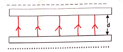
- Complete the diagram to show the electric field pattern in the space between the plates. (2marks)
- Without changing the distance d between the plates, suggest one method by which you could increase the capacitance. (1mark)
Increase the area of overlap
Introduce a dielectric - State a device where a variable air capacitor could be used. (1mark)
Tuning circuits of electronics
- Figure 11 below shows a circuit of three capacitors and a d.c. source.
Determine the p.d. across A.B. (3marks)
Total capacitance
(10 x 15) + 5
10 + 15
= 11μF
Total charge Q = CV
Q = 11 x 12 = 132μC
Charge on μF & 15μF will be 6 x 12 = 72μC
Voltage across 10μF
V = Q/C = (72/10)V
= 7.2V
- A proof plane is used to touch side B of the conductor and then the cap of an uncharged electroscope. This is then repeated with side A.
- Figure 12 below shows the path of a ray of yellow light through a glass prism of refractive index 1.60.
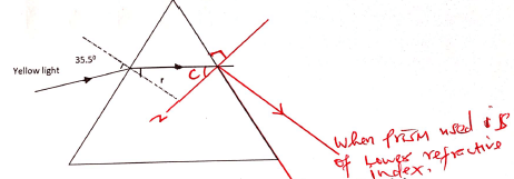
- Determine the value of angle r. (3marks)
n = sin = 1.6 = sin 35.5
sin r sin r
son r = 0.3629
r = sin-10.3629 = 21.28º - Show on the figure the critical angle, c and determine its value. (3marks)
n = 1
SinC
SinC = 1 = 0.625
1.6
C = sin-10.625
= 38.68º - Determine the speed of light in glass given that the speed of light in vacuum.
(C = 3.0x10⁸m/s) (3marks)
n = V1 ⇒ 1.6 = 3.0 x 10⁸
Vg Vg
Vg = 3.0 x 108 = 1.875 x 10⁸ m/s
1.6 - On the same figure, sketch the path of the light after striking the prism if the prism was replaced by another of similar shape but lower refractive index. (Use dotted line for your answer) (2marks)
On the diagram
- Determine the value of angle r. (3marks)
- Figure 13 below shows the circuit of a simple telephone receiver. When a person speaks into the microphone on the other side a varying current flows.
- State the reason why the solenoids are wound in opposite directions around the soft-iron pole pieces as shown. (1mark)
To create opposite polarity of the soft iron cores so as to create magnetic field - Explain how the speech current from the microphone is converted into sound in the receiver. (3marks)
Varying speech current flowing in the windings of the coil causes a varying magnetic field of the frequency of the speech current
The varying magnetic field attracts the iron diaphram which vibrates at the same frequency and reproduce the sound - State and explain the effect of replacing the soft iron pole pieces with steel pole pieces. (3marks)
The core becomed a permanent magnet, once magnetised
The core attrats the iron diaphragm once and remains there
It does not vibrate, therefore it does not produce the sound
- State the reason why the solenoids are wound in opposite directions around the soft-iron pole pieces as shown. (1mark)
-
- State the Ohms’ law. (1mark)
The current flowing through a conductor is directly proportional to the p.d accross its ends provided the temperature and other physical conditions remain constant - Three resistors x,y and z where x = 200 Ω, y = 100 Ω and z is unknown resistance are connected in parallel. This arrangement is then placed in a circuit and current passing through, and potential difference across its measured the table below shows the result.
V = IRp.d(V) 2.0 4.0 6.0 8.0 10.0 12.0 Current(l) (A) 0.10 0.20 0.30 0.40 0.50 0.60 - Plot a graph of p.d against current. (5marks)
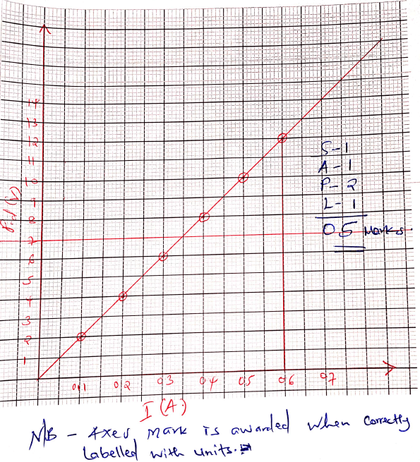
- Use your graph to calculate the value of unknown resistance. (3marks)
from V = IR
Slope = 12 - 0 = 20
0.6 - 0
But 1 + 1 + 1 = 1
200 100 x 20
x = 25
- Plot a graph of p.d against current. (5marks)
- Four resistors are connected in a circuit as shown in the diagram below
Calculate the p.d across AB. (3marks)
R = ½ + ½ + 1/3
R = 4/3
R = ¾ = 0.75
Rsens = 4 + 0.75 = 4.75
E = I(R + r)
12 = I(4.75 + 0.2)
I = 12 = 2.424A
4.95
P.D across 4
4 x 2.424 = 9.696V
therefore p.d across AB
= 12-9.696
= 2.304V
- State the Ohms’ law. (1mark)
Join our whatsapp group for latest updates
Tap Here to Download for 50/-
Get on WhatsApp for 50/-
Download Physics Paper 2 Questions and Answers - Momaliche Joint Mock Exams 2021/2022.
Tap Here to Download for 50/-
Get on WhatsApp for 50/-
Why download?
- ✔ To read offline at any time.
- ✔ To Print at your convenience
- ✔ Share Easily with Friends / Students