
INSTRUCTIONS TO CANDIDATES
- Write your name and your index number in the spaces provided above.
- This paper consists of two sections A and B
- Answer all questions in section A and B in the space provided
- All working must be shown in the spaces provided in this booklet.
- Mathematical tables and silent electronic calculators may be used
FOR EXAMINER USE
|
Section |
Question |
Max. score |
Candidate’s score |
|
A |
1-12 |
25 |
|
|
B |
13 |
11 |
|
|
14 |
06 |
||
|
15 |
14 |
||
|
16 |
15 |
||
|
17 |
09 |
||
|
TOTAL SCORE |
80 |
||

QUESTIONS
SECTION A – 25 MARKS
- Figure 1 shows a ray of light incident on a plane mirror.
Figure 1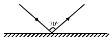
The plane mirror is then rotated clockwise through an angle of 200 keeping the incident ray fixed. Determine the new angle of reflection. (2 Marks) - A dry cell is not recharged once used up. However when used well, it can serve one for some time. State the precautions necessary when using it other than storing it in dry condition. (2 Marks)
- A charged rod A is used to charge another rod B by contact. When rod B is brought close to a charged acetate rod, repulsion occurs. State the type of charge on rod A. (1 Mk)
- A nail is electrically magnetised, it attracts an increasing number of pins as the magnetising current increase. After some time it can no longer attract any more pins. Explain this observation domain theory.(2 Marks)
- Figure 2 below shows a current carrying vertically right wire at right angle to a cardboard. Iron fillings are sprinkled on the card and card slightly tapped.
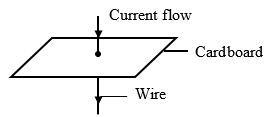
Draw and indicate the direction of the magnetic field pattern displayed on the card. (2 Marks) - Figure 3 below shows a wave profile for a wave whose frequency is 2.5HZ
Figure 3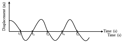
Determine the value of t3 (2marks) - An electric kettle has an element of resistance 28.8Ω. It is operating from a 240V main supply. Determine its power rating. (3 Marks)
- Distinguish between intrinsic and extrinsic semi-conductor. (1 Mark)
- The following is part of a radioactive series.
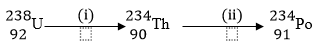
Identify the radioactive particles emitted in stages (i) and (ii) (2 Marks)- ..............................................
- ..............................................
- Figure 4 shows light passing through a transparent block.
Figure 4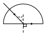
Determine the refractive index of the block. (3 Marks) - Figure 5 shows part of the electromagnetic spectrum.
Figure 5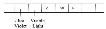
Identify radiation W and state one of its uses.(2marks) - Figure 6 shows a permanent magnet placed near a solenoid connected to a source of e.m.f.
Figure 6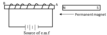
- State and explain what is observed when the North – pole of the permanent magnet is brought to end A. (2marks)
- State the law applied (1mark)
SECTION B – 55 MARKS
Answer ALL questions in the spaces provided after each section of the question
-
- A strong positive charged rod is brought close to the cap of a charged electroscope from a high Position. It is observed
- State the charge on the electroscope (1 Mark)
- Explain this observation (2 Marks)
- A parallel – plate capacitor is connected to an electroscope as shown in Fig. 7 below.
Figure 7
State and explain the behaviour of the leaf when the distance (d) between the plates is increased (2 Marks) - Figure 8 shows an arrangement of capacitors to a 12V d.c. supply.
Figure 8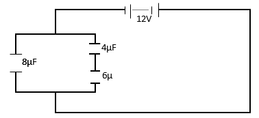
Determine- Effective capacitance (3 Marks)
- Charge across the 8µF capacitor. (3 Marks)
- A strong positive charged rod is brought close to the cap of a charged electroscope from a high Position. It is observed
-
- The figure 9 below shows a step-up transformer commonly used at a power station.
Figure 9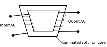
What is meant by a step-up transformer? (1 Mark) - Why does a transformer work with AC only? (1 Mark)
- What is the purpose of the soft iron core? (1 Mark)
- State four ways in which power is lost in a transformer (1 Mark )
- Why is the e.m.f. produced at a power station stepped up to high voltage for long distance transmission (2 Marks)
- The figure 9 below shows a step-up transformer commonly used at a power station.
-
- Figure 10 shows the trace on the screen of a.c. signal connected to the Y-plates of a C.R.O with the time – base on.
Figure 10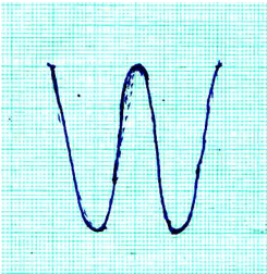
Given that the time base control is 10ms/cm and the Y-gain is at 120V/cm determine- The frequency of the a.c. signal (3 Marks)
- The peak voltage of the input signal (3 Marks)
- State what would be observed on the screen if the time base is switched off (1 Mark)
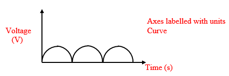
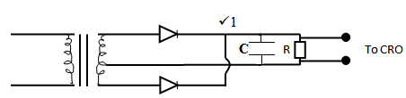
- Figure 11 shows a circuit whose output voltage with time as displayed on the CRO screen. (2 Marks)
Figure 11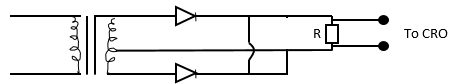
- Sketch a graph to show the variation of output voltage with time as displayed on the CRO screen. ( 2 Marks)
- Show on the diagram (Figure 11) how a capacitor should be connected to smooth the output voltage (1 Mark)
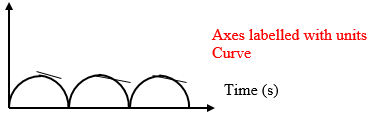
- Sketch a curve of smoothed output voltage against time. (2 Marks)
- Figure 10 shows the trace on the screen of a.c. signal connected to the Y-plates of a C.R.O with the time – base on.
-
- X-rays are used for detecting cracks inside metal beams: State the type of X-rays used. (1mark)
- The figure 12 below shows the feature of an X-ray tube.
Figure 12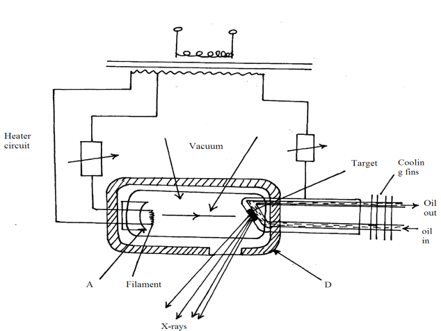
- Name the parts labelled A,B,C,D. (2marks)
- Explain how X-rays are produced in the tube. (3marks)
- During the operation of the tube, the target becomes very hot explain. (2marks)
- Name one feature of the X-ray tube which makes it possible for heat to be conducted away safely without causing overheating. (1mark)
- Explain the use of X-ray in textile industries. (3marks)
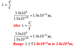
- The frequency of X-rays ranges from 3.0x10¹⁶Hz to 3.0x10¹⁹Hz. determine the range of wavelength . (take C =3.0x10⁸m/s) (3marks)
-
- With the aid of a labelled diagram, explain how the focal length of a convex lens may be estimated by focusing a distant object.(3marks)
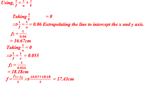
- The graph below shows values obtained in an experiment to determine the focal length of a convex lens. Use the graph to determine the focal-length of the lens.(4 marks)
- An object is placed 30cm infront of a converging lens of focal length 20cm.
- By calculation determine the position of the image. (2 Marks)
- State the nature of the image (1 Mark)
MARKING SCHEME
- Figure 1 shows a ray of light incident on a plane mirror.
Figure 1
The plane mirror is then rotated clockwise through an angle of 200 keeping the incident ray fixed. Determine the new angle of reflection. (2 Marks)
Angle of incidence = 70º = 35º
2
Angle of reflection = 35º
New angle of reflection = 354 + (2 x 20)
= 75º - A dry cell is not recharged once used up. However when used well, it can serve one for some time. State the precautions necessary when using it other than storing it in dry condition. (2 Marks)
Do not draw large current from it
Do not short circuit its terminals - A charged rod A is used to charge another rod B by contact. When rod B is brought close to a charged acetate rod, repulsion occurs. State the type of charge on rod A. (1 Mk)
Charge on rod A is positive
- A nail is electrically magnetised, it attracts an increasing number of pins as the magnetising current increase. After some time it can no longer attract any more pins. Explain this observation domain theory.(2 Marks)
Nail attains magnetic saturation
All dipoles are aligned - Figure 2 below shows a current carrying vertically right wire at right angle to a cardboard. Iron fillings are sprinkled on the card and card slightly tapped.
Draw and indicate the direction of the magnetic field pattern displayed on the card. (2 Marks)
Pattern
Direction - Figure 3 below shows a wave profile for a wave whose frequency is 2.5HZ
Figure 3
Determine the value of t3 (2marks)
T = 1/f = 1/2.5
= 0.4 Sec
t3 =3/4 x 0.4
= 0.3 sec - An electric kettle has an element of resistance 28.8Ω. It is operating from a 240V main supply. Determine its power rating. (3 Marks)
P = IV
= v/R(v)
=v2/R = (240)2/28.8
= 2000W - Distinguish between intrinsic and extrinsic semi-conductor. (1 Mark)
Intrinsic – Pure semiconductor Both correct
Extrinsic – An impure semi-conductor - The following is part of a radioactive series.
Identify the radioactive particles emitted in stages (i) and (ii) (2 Marks)- Alpha particles
- Beta particle
- Figure 4 shows light passing through a transparent block.
Figure 4
Determine the refractive index of the block. (3 Marks)
C = 41.80
n = 1
sin C
= 1 = 1.500
sin 41.8º - Figure 5 shows part of the electromagnetic spectrum.
Figure 5
Identify radiation W and state one of its uses.(2marks)
W – Microwave
Uses – Cooking
Communication - Figure 6 shows a permanent magnet placed near a solenoid connected to a source of e.m.f.
Figure 6- State and explain what is observed when the North – pole of the permanent magnet is brought to end A. (2marks)
End A and the Norrth pole repels
Current flows to form a North pole at A - State the law applied (1mark)
Lenz’s law
- State and explain what is observed when the North – pole of the permanent magnet is brought to end A. (2marks)
SECTION B – 55 MARKS
Answer ALL questions in the spaces provided after each section of the question
-
- A strong positive charged rod is brought close to the cap of a charged electroscope from a high Position. It is observed
- State the charge on the electroscope (1 Mark)
Negative - Explain this observation (2 Marks)
The rod attracts the negative charges from the leaf and the plate to the cap to make the leaf and plate neutral
One coming closer, more negative charges are attracted and the leaf and the plate becomes positive thus the leaf diverges
- State the charge on the electroscope (1 Mark)
- A parallel – plate capacitor is connected to an electroscope as shown in Fig. 7 below.
Figure 7
State and explain the behaviour of the leaf when the distance (d) between the plates is increased (2 Marks)
The leaf divergence increases.
- As d- increases, potential difference (V) across the plates increases, thus the capacitance of the capacitors reduces, and some charges moves to the electroscope.
From, C = Q/V
Keeping Q – Constant as V – Increases C – Decrease - Figure 8 shows an arrangement of capacitors to a 12V d.c. supply.
Figure 8
Determine- Effective capacitance (3 Marks)
CT = 4 x 6 + 8
4 + 6
= 10.4µF OR 1.04 x 10⁻⁵F - Charge across the 8µF capacitor. (3 Marks)
Q = CV
= 8 x 10-6 x 12
= 9.6 x 10⁻⁵ C (with V units)
- Effective capacitance (3 Marks)
- A strong positive charged rod is brought close to the cap of a charged electroscope from a high Position. It is observed
-
- The figure 9 below shows a step-up transformer commonly used at a power station.
Figure 9
What is meant by a step-up transformer? (1 Mark)
It is a transformer that is used to increase the value of the output voltage or the ratio of the number of turns
- Why does a transformer work with AC only? (1 Mark)
AC charges or reverses hence it brings about a charge in magnetic flux in the primary coils. 1
- What is the purpose of the soft iron core? (1 Mark)
It is used to link the two coils hence concentrating field lines and preventing flux loss. 1
- State four ways in which power is lost in a transformer (1 Mark )
– Hysteresis
- Eddy currents
- Flux leakages
- Resistance of copper wires (any one correct) - Why is the e.m.f. produced at a power station stepped up to high voltage for long distance transmission (2 Marks)
At high voltages, the current in the transmitting cables is less, hence power loss (I2R) is greately reduced.
- The figure 9 below shows a step-up transformer commonly used at a power station.
-
- Figure 10 shows the trace on the screen of a.c. signal connected to the Y-plates of a C.R.O with the time – base on.
Figure 10
Given that the time base control is 10ms/cm and the Y-gain is at 120V/cm determine- The frequency of the a.c. signal (3 Marks)
Time for 2 cycles shown = 10 x 4cm
= 40ms
T = 40/2 = 20 ms
f = 1/T
= 1
20 x 10-3
= 50HZ - The peak voltage of the input signal (3 Marks)
Voltage = y – gain x displacement
= 120 x 2
= 240V - State what would be observed on the screen if the time base is switched off (1 Mark)
The trace on the screen would be a vertical line
- The frequency of the a.c. signal (3 Marks)
- Figure 11 shows a circuit whose output voltage with time as displayed on the CRO screen. (2 Marks)
Figure 11- Sketch a graph to show the variation of output voltage with time as displayed on the CRO screen. ( 2 Marks)
- Show on the diagram (Figure 11) how a capacitor should be connected to smooth the output voltage (1 Mark)
- Sketch a curve of smoothed output voltage against time. (2 Marks)
- Sketch a graph to show the variation of output voltage with time as displayed on the CRO screen. ( 2 Marks)
- Figure 10 shows the trace on the screen of a.c. signal connected to the Y-plates of a C.R.O with the time – base on.
-
- X-rays are used for detecting cracks inside metal beams: State the type of X-rays used. (1mark)
Hard X-rays; - The figure 12 below shows the feature of an X-ray tube.
Figure 12- Name the parts labelled A,B,C,D. (2marks)
A focusing cathode, B-Electron beam, C-copper anode, D- lead shield ; ½ each. - Explain how X-rays are produced in the tube. (3marks)
Filament is heated it heats the cathode and electrons are emitted thermionically; emitted electrons are accelerated to the target by accelerating potential; upon hitting the target, X-rays are produced;
- During the operation of the tube, the target becomes very hot explain. (2marks)
The moving electrons possesses kinetic energy; most of this energy is converted into heat when the electrons meet the target.
- Name one feature of the X-ray tube which makes it possible for heat to be conducted away safely without causing overheating. (1mark)
copper cooling fins
- Explain the use of X-ray in textile industries. (3marks)
X-rays are able to ionise the air particles; ionises air particles are used to discharge cloth materials to remove static charges; the static charges on the cloth can cause fire outbreak;
- The frequency of X-rays ranges from 3.0x10¹⁶Hz to 3.0x10¹⁹Hz. determine the range of wavelength . (take C =3.0x10⁸m/s) (3marks)
- Name the parts labelled A,B,C,D. (2marks)
- X-rays are used for detecting cracks inside metal beams: State the type of X-rays used. (1mark)
-
- With the aid of a labelled diagram, explain how the focal length of a convex lens may be estimated by focusing a distant object.(3marks)
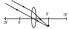
Diagram (1) focus a distant object onto a screen distance between the image and the lens is the focal length
- The graph below shows values obtained in an experiment to determine the focal length of a convex lens. Use the graph to determine the focal-length of the lens.(4 marks)
- An object is placed 30cm infront of a converging lens of focal length 20cm.
- By calculation determine the position of the image. (2 Marks)
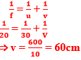
Image is 60cm from the lens on the opposite side to that object.√ - State the nature of the image (1 Mark)
The image is real
- By calculation determine the position of the image. (2 Marks)
- With the aid of a labelled diagram, explain how the focal length of a convex lens may be estimated by focusing a distant object.(3marks)
Download Physics Paper 2 Questions and Answers - Kigumo Mocks 2021 Exams.
Tap Here to Download for 50/-
Get on WhatsApp for 50/-
Why download?
- ✔ To read offline at any time.
- ✔ To Print at your convenience
- ✔ Share Easily with Friends / Students