Figure 8 shows two straight conductors P and Q connected to a battery and a variable resistor.
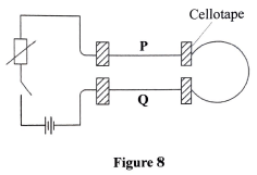
- Using arrows, indicate on the diagram the direction of current that flows through P and Q when the switch is closed.
- State what is observed as the current flows through the conductors.
- Explain the observation in (2).